ACHROMATIC WAVEPLATES
When any form of polarized light is incident on a birefringent waveplate, it is resolved into two linearly polarized components which vibrate perpendicular to each other and travel with different velocities in the crystal. The beams emerge with a phase delay. This phase delay or retardation is dependent on birefringence of the crystal. Birefringence at a specified wavelength is the difference in refractive indices of the extraordinary and ordinary resolved components. Because of dispersion of birefringence i.e. it's dependence on wavelength, there is a variation of retardation with wavelength. In an achromatic retarder, this variation is minimized by fabricating a double plate retarder using two different birefringent crystals of magnesium fluoride and crystalline quartz. Achromatic quarter and half wave retarders are optimized for three standard wavelength regions of 400 to 700 nm, 700 to 1000 nm and 1000 to 1600 nm. Standard waveplates are cemented or air-spaced type and are available in clear aperture diameters of 12 mm and 22 mm. Non standard waveplates optimized for different wavelength regions and clear apertures are available on special order.
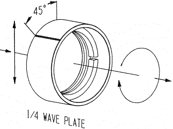
quarter wave retarder with fast axis marked on the cell
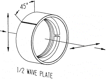
half wave retarder with fast axis marked on the cell
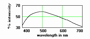
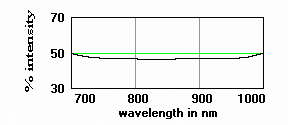
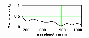
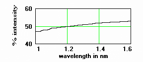
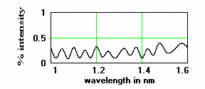
WAVEPLATE BETWEEN TWO OPEN POLARIZERS AT 45 DEGREES AZIMUTH - % INTENSITY VS WAVELENGTH
quarter wave achromatic optimized for 400 to 700 nm
quarter wave achromatic optimized for 700 to 1100 nm
quarter wave achromatic optimized for 400 to 700 nm

half wave achromatic optimized for 700 to 1100 nm
Specifications:
surface flatness : at least quarter wave @ 633 nm over the clear aperture
surface quality : 40-20 scratch dig
reflectivity per surface : uncoated about 4%; BB coating 1.5% average; HEAR coated .7% average
Please visit our Anti Reflection Coating page on this website for coating plots.
|
CEMENTED / AIR SPACED ACHROMATIC QUARTER AND HALF WAVE RETARDERS
|
|
Catalog Number |
Clear Aperture Diameter (mm) |
Type |
Retardation in waves |
WL* Range 400-700 nm 700-1000 nm 1000-1600 nm |
Type of Anti Reflection Coating |
Mount Dimensions ( Inches) |
|
|
Outside Diameter +/- .002 |
Length +/- .005 |
||||||
|
WPAC4-12 WL Range*-UN |
12 | Cemented | Quarter | WL Range* | Uncoated | .750 | .500 |
|
WPAC2-12 WL Range*-HEAR |
12 | Cemented | Half | WL Range* | HEAR Coated | .750 | .500 |
|
WPAC4-22 WL Range*-UN |
22 | Cemented | Quarter | WL Range* | Uncoated | 1.125 | .500 |
|
WPAC2-22 WL Range*-HEAR |
22 | Cemented | Half | WL Range* | HEAR Coated | 1.125 | .500 |
|
MWPAA4-12 WL Range*-UN |
12 | Air Spaced | Quarter | WL Range* | Uncoated | .750 | .500 |
|
MWPAA2-12 WL Range*-HEAR |
12 | Air Spaced | Half | WL Range* | HEAR Coated | .750 | .500 |
|
MWPAA4-22 WL Range*-UN |
22 | Air Spaced | Quarter | WL Range* | Uncoated | 1.125 | .500 |
|
MWPAA2-22 WL Range*-HEAR |
22 | Air Spaced | Half | WL Range* | HEAR Coated | 1.125 | .500 |
Achromatic cemented waveplates are supplied unmounted. Optional mounts for these are available upon request.
